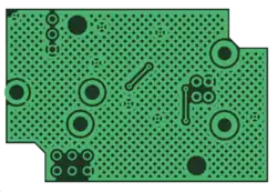

In electronics, the term copper pour refers to an area on a printed circuit board filled with copper (the metal used to make connections in printed circuit boards). Copper pour is commonly used to create a ground plane. Another reason for using copper pour is to reduce the amount of etching fluid used during manufacturing.
A distinctive feature of copper pour is the backoff (or stand-off) - a certain distance between the copper pour and any tracks or pads not belonging to the same electrical net. A copper pour therefore looks like it flows around other components, with the exception of pads which are connected to the copper pour using thermal connections.
PCB designers today almost invariably use completely solid areas of copper pour that completely cover the remaining area outside those tracks, pads, and stand-off regions. Many early PCBs have a "hatched copper pour", sometimes called a "cherry pie lattice".[1]
While solid copper pour provides better resistive characteristics, hatched copper pour is used to balance the heat and dilatation on both sides of the board in order to avoid warping of certain substrate.[2] Heating might cause gas bubbles between solid copper pour and certain substrates. Furthermore, it might be possible to adjust the impedance of high frequency traces by using hatched copper pour in order to reach better signal quality.[3]
See also
References
- ↑ "PWB design flow: Working with polygons". Archived from the original on 2018-06-24. Retrieved 2018-06-24.
- ↑ "Copper pour or traces?". electronicspoint.com. 2007-08-01. Archived from the original on 2018-06-24. Retrieved 2011-08-31.
- ↑ "Solid ground-plane vs Hatched ground-plane". electronics.stackexchange.com. 2010-10-12. Archived from the original on 2016-08-19. Retrieved 2011-09-01.