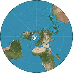

The stereographic projection, also known as the planisphere projection or the azimuthal conformal projection, is a conformal map projection whose use dates back to antiquity. Like the orthographic projection and gnomonic projection, the stereographic projection is an azimuthal projection, and when on a sphere, also a perspective projection.
On an ellipsoid, the perspective definition of the stereographic projection is not conformal, and adjustments must be made to preserve its azimuthal and conformal properties. The universal polar stereographic coordinate system uses one such ellipsoidal implementation.
History

The stereographic projection was likely known in its polar aspect to the ancient Egyptians, though its invention is often credited to Hipparchus, who was the first Greek to use it. Its oblique aspect was used by Greek Mathematician Theon of Alexandria in the fourth century, and its equatorial aspect was used by Arab astronomer Al-Zarkali in the eleventh century. The earliest written description of it is Ptolemy's Planisphaerium, which calls it the "planisphere projection".
The stereographic projection was exclusively used for star charts until 1507, when Walther Ludd of St. Dié, Lorraine created the first known instance of a stereographic projection of the Earth's surface. Its popularity in cartography increased after Rumold Mercator used its equatorial aspect for his 1595 atlas.[1] It subsequently saw frequent use throughout the seventeenth century with its equatorial aspect being used for maps of the Eastern and Western hemispheres.[2]
In 1695, Edmond Halley, motivated by his interest in star charts, published the first mathematical proof that this map is conformal.[3] He used the recently established tools of calculus, invented by his friend Isaac Newton.
Formulae
The spherical form of the stereographic projection is usually expressed in polar coordinates:
where is the radius of the sphere, and and are the latitude and longitude, respectively.
The sphere is normally chosen to model the Earth when the extent of the mapped region exceeds a few hundred kilometers in length in both dimensions. For maps of smaller regions, an ellipsoidal model must be chosen if greater accuracy is required.[1]
The ellipsoidal form of the polar ellipsoidal projection uses conformal latitude. There are various forms of transverse or oblique stereographic projections of ellipsoids. One method uses double projection via a conformal sphere, while other methods do not.
Examples of transverse or oblique stereographic projections include the Miller Oblated Stereographic[4] and the Roussilhe oblique stereographic projection.[2]
Properties
As an azimuthal projection, the stereographic projection faithfully represents the relative directions of all great circles passing through its center point. As a conformal projection, it faithfully represents angles everywhere. In addition, in its spherical form, the stereographic projection is the only map projection that renders all small circles as circles.

The spherical form of the stereographic projection is equivalent to a perspective projection where the point of perspective is on the point on the globe opposite the center point of the map.
Because the expression for diverges as approaches , the stereographic projection is infinitely large, and showing the South Pole (for a map centered on the North Pole) is impossible. However, it is possible to show points arbitrarily close to the South Pole as long as the boundaries of the map are extended far enough.[1]
Derived projections
The parallels on the Gall stereographic projection are distributed with the same spacing as those on the central meridian of the transverse stereographic projection.
The GS50 projection is formed by mapping the oblique stereographic projection to the complex plane and then transforming points on it via a tenth-order polynomial.
References
- 1 2 3 Snyder, John P. 1987. "Map Projections---A Working Manual". Professional Paper. United States Geological Survey. 1395: 154--163. ISBN 0-226-76746-9.
- 1 2 Snyder, John P. (1993). Flattening the Earth: Two Thousand Years of Map Projections p.~169. Chicago and London: The University of Chicago Press. ISBN 0-226-76746-9.
- ↑ Timothy Feeman. 2002. "Portraits of the Earth: A Mathematician Looks at Maps". American Mathematical Society.
- ↑ Sprinsky, William H.; Snyder, John P. (1986). "The Miller Oblated Stereographic Projection for Africa, Europe, Asia and Australasia". The American Cartographer. 13 (3): 253–261. doi:10.1559/152304086783899908.
