In power engineering, nodal admittance matrix (or just admittance matrix) is an N x N matrix describing a linear power system with N buses. It represents the nodal admittance of the buses in a power system. In realistic systems which contain thousands of buses, the admittance matrix is quite sparse. Each bus in a real power system is usually connected to only a few other buses through the transmission lines.[1] The nodal admittance matrix is used in the formulation of the power flow problem.
Context
Electric power transmission needs optimization in order to determine the necessary real and reactive power flows in a system for a given set of loads, as well as the voltages and currents in the system. Power flow studies are used not only to analyze current power flow situations, but also to plan ahead for anticipated disturbances to the system, such as the loss of a transmission line to maintenance and repairs. The power flow study would determine whether or not the system could continue functioning properly without the transmission line. Only computer simulation allows the complex handling required in power flow analysis because in most realistic situations the system is very complex and extensive and would be impractical to solve by hand. The admittance matrix is a tool in that domain. It provides a method of systematically reducing a complex system to a matrix that can be solved by a computer program. The equations used to construct the admittance matrix come from the application of Kirchhoff's current law and Kirchhoff's voltage law to a circuit with steady-state sinusoidal operation. These laws give us that the sum of currents entering a node in the circuit is zero, and the sum of voltages around a closed loop starting and ending at a node is also zero. These principles are applied to all the nodes in a power flow system and thereby determine the elements of the admittance matrix, which represents the admittance relationships between nodes, which then determine the voltages, currents and power flows in the system.
Construction from a single line diagram
The nodal admittance matrix of a power system is a form of Laplacian matrix of the nodal admittance diagram of the power system, which is derived by the application of Kirchhoff's laws to the admittance diagram of the power system. Starting from the single line diagram of a power system, the nodal admittance diagram is derived by:
- replacing each line in the diagram with its equivalent admittance, and
- converting all voltage sources are converted to their equivalent current source.
Consider an admittance graph with buses. The vector of bus voltages, , is an vector where is the voltage of bus , and vector of bus current injections, , is an vector where is the cumulative current injected at bus by all loads and sources connected to the bus. The admittance between buses and is a complex number , and is the sum of the admittance of all lines connecting busses and . The admittance between the bus and ground is , and is the sum of the admittance of all the loads connected to bus .


Consider the current injection, , into bus . Applying Kirchhoff's current law

where is the current from bus to bus for and is the current from bus to ground through the bus load. Applying Ohm's law to the admittance diagram, the bus voltages and the line and load currents are linked by the relation


Therefore,

This relation can be written succinctly in matrix form using the admittance matrix. The nodal admittance matrix is a matrix such that bus voltage and current injection satisfy Ohm's law


in vector format. The entries of are then determined by the equations for the current injections into buses, resulting in

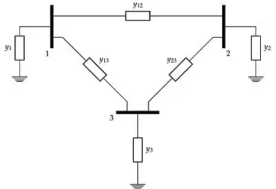
As an example, consider the admittance diagram of a fully connected three bus network of figure 1. The admittance matrix derived from the three bus network in the figure is:

The diagonal entries are called the self-admittances of the network nodes. The non-diagonal entries are the mutual admittances of the nodes corresponding to the subscripts of the entry. The admittance matrix is typically a symmetric matrix as . However, extensions of the line model may make asymmetrical. For instance, modeling phase-shifting transformers, results in a Hermitian admittance matrix.[2]


Applications
The admittance matrix is most often used in the formulation of the power flow problem.[3][4]
See also
References
- ↑ Grainger, John (1994). Power System Analysis. McGraw-Hill Science/Engineering/Math. ISBN 978-0070612938.
- ↑ Saadat, Hadi (1999). "6.7 Tap changing transformers". Power System Analysis. United Kingdom: WCB/McGraw-Hill. ISBN 978-0075616344.
- ↑ McCalley, James. "The Power Flow Equations" (PDF). Iowa State Engineering.
- ↑ Saadat, Hadi (1999). Power System Analysis. United Kingdom: WCB/McGraw-Hill. ISBN 978-0075616344.