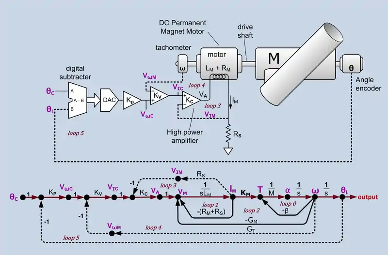
Minor loop feedback is a classical method used to design stable robust linear feedback control systems using feedback loops around sub-systems within the overall feedback loop.[1] The method is sometimes called minor loop synthesis in college textbooks,[1][2] some government documents.[3]
The method is suitable for design by graphical methods and was used before digital computers became available. In World War 2 this method was used to design Gun laying control systems.[4] It is still used now, but not always referred to by name. It is often discussed within the context of Bode plot methods. Minor loop feedback can be used to stabilize opamps.[5]
Example
Telescope position servo

This example is slightly simplified (no gears between the motor and the load) from the control system for the Harlan J. Smith Telescope at the McDonald Observatory.[6] In the figure there are three feedback loops: current control loop, velocity control loop and position control loop. The last is the main loop. The other two are minor loops. The forward path, considering only the forward path without the minor loop feedback, has three unavoidable phase shifting stages. The motor inductance and winding resistance form a low-pass filter with a bandwidth around 200 Hz. Acceleration to velocity is an integrator and velocity to position is an integrator. This would have a total phase shift of 180 to 270 degrees. Simply connecting position feedback would almost always result in unstable behaviour.
Current control loop
The innermost loop regulates the current in the torque motor. This type of motor creates torque that is nearly proportional to the rotor current, even if it is forced to turn backward. Because of the action of the commutator, there are instances when two rotor windings are simultaneously energized. If the motor was driven by a voltage controlled voltage source, the current would roughly double, as would the torque. By sensing the current with a small sensing resister (RS) and feeding that voltage back to the inverting input of the drive amplifier, the amplifier becomes a voltage controlled current source. With constant current, when two windings are energized, they share the current and the variation of torque is on the order of 10%.
Velocity control loop
The next innermost loop regulates motor speed. The voltage signal from the Tachometer (a small permanent magnet DC generator) is proportional to the angular velocity of the motor. This signal is fed back to the inverting input of the velocity control amplifier (KV). The velocity control system makes the system 'stiffer' when presented with torque variations such as wind, movement about the second axis and torque ripple from the motor.
Position control loop
The outermost loop, the main loop, regulates load position. In this example, position feedback of the actual load position is presented by a Rotary encoder that produces a binary output code. The actual position is compared to the desired position by a digital subtracter that drives a DAC (Digital-to-analog converter) that drives the position control amplifier (KP). Position control allows the servo to compensate for sag and for slight position ripple caused by gears (not shown) between the motor and the telescope
Synthesis
The usual design procedure is to design the innermost subsystem (the current control loop in the telescope example) using local feedback to linearize and flatten the gain. Stability is generally assured by Bode plot methods. Usually, the bandwidth is made as wide as possible. Then the next loop (the velocity loop in the telescope example) is designed. The bandwidth of this sub-system is set to be a factor of 3 to 5 less than the bandwidth of the enclosed system. This process continues with each loop having less bandwidth than the bandwidth of the enclosed system. As long as the bandwidth of each loop is less than the bandwidth of the enclosed sub-system by a factor of 3 to 5, the phase shift of the enclosed system can be neglected, i.e. the sub-system can be treated as simple flat gain. Since the bandwidth of each sub-system is less than the bandwidth of the system it encloses, it is desirable to make the bandwidth of each sub-system as large as possible so that there is enough bandwidth in the outermost loop. The system is often expressed as a Signal-flow graph and its overall transfer function can be computed from Mason's Gain Formula.
References
- 1 2 Kuo, Benjamin C. (1991), Automatic Control Systems, Prentice-Hall, ISBN 978-0-13-051046-4
- ↑ Brown, Gordon S.; Campbell, Donald P. (1948), Principles of Servomechanisms, John Wiley & Sons
- ↑ Leininger, Gary, Application of the MNA Design Method to a Non-Linear Turbofan Engine (PDF), retrieved 18 Mar 2011
- ↑ Bennett, Stuart, A brief History of Automatic Control (PDF), p. 20, archived from the original (PDF) on 2011-10-07, retrieved 18 Mar 2011
- ↑ Lundberg, Internal and external op-amp compensation: a control-centric tutorial, retrieved 18 Mar 2011
- ↑ Dittmar, David (1–5 Mar 1971). Conference on Large Telescope Design, Proceedings of an ESO (European Southern Observatory)/CERN (Conseil Europeen pour la Recherche Nucleaire) Conference. Geneva, Switzerland (published June 1971). p. 383.
External links
- Li, Yunfeng and Roberto Horowitz. "Mechatronics of Electrostatic Microactuators for Computer Disk Drive Dual-Stage Servo Systems." IEEE/ASME Transactions on Mechatronics, Vol. 6 No. 2. June 2001.
- Dawson, Joel L. "Feedback Systems." MIT.
- Large Telescope Conference 1971, contains full text of Dittmar's presentation.