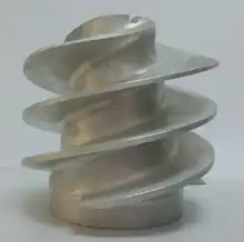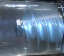
An inducer is the axial inlet portion of a centrifugal pump rotor, the function of which is to raise the inlet head by an amount sufficient to prevent significant cavitation in the following pump stage.[1] It is used in applications in which the inlet pressure of a pump is close to the vapor pressure of the pumped liquid. Inducers are frequently included in design of turbopumps for liquid propellant rocket engines, although they are used in other applications which require high suction performance.[2] It does not increase NPSHa but decreases NPSHr for Pump.

Use in rocketry
In order to achieve high delta-v, the structural mass of a launch vehicle should be as low as possible. Liquid fuel tanks can be constructed lighter if the pressure within those tanks is kept low. Typically, for pump-fed rocket engines, the propellant tank pressures (and masses) are 1/10 to 1/40 of those in a pressure-fed rocket.[3] The structural weight constraint also makes the rotating speed of the turbopump rotor as high as possible. For example, the rotating speed of the oxygen turbopump of the Japanese LE-7 rocket engine is 18300rpm.[3] These two factors above combine to make the pump impeller very susceptible to cavitation. If cavitation occurs in the impeller, the performance of the pump will be severely degraded and the pump itself may be damaged.
References
- ↑ NASA SP-8052 Liquid rocket engine turbopump inducers. NASA.
- ↑ Japikse, David. "Overview of Industrial and Rocket Turbopump Inducer Design" (PDF). Concepts NREC. Retrieved 17 May 2014.
- 1 2 Sutton, George P. (2001). Rocket propulsion elements (7th ed.) (PDF). John Wiley&Sons. pp. 218, 363. Archived from the original (PDF) on 2013-01-02.