| By transport mode | ||||||||||||||||||||||||||||||||||||||||||||||||||||||||||||||||||||||||||||||||||||||||||||||||||||||||||||||||
|---|---|---|---|---|---|---|---|---|---|---|---|---|---|---|---|---|---|---|---|---|---|---|---|---|---|---|---|---|---|---|---|---|---|---|---|---|---|---|---|---|---|---|---|---|---|---|---|---|---|---|---|---|---|---|---|---|---|---|---|---|---|---|---|---|---|---|---|---|---|---|---|---|---|---|---|---|---|---|---|---|---|---|---|---|---|---|---|---|---|---|---|---|---|---|---|---|---|---|---|---|---|---|---|---|---|---|---|---|---|---|---|---|
| By size (list) | ||||||||||||||||||||||||||||||||||||||||||||||||||||||||||||||||||||||||||||||||||||||||||||||||||||||||||||||||
| ||||||||||||||||||||||||||||||||||||||||||||||||||||||||||||||||||||||||||||||||||||||||||||||||||||||||||||||||
| Change of gauge | ||||||||||||||||||||||||||||||||||||||||||||||||||||||||||||||||||||||||||||||||||||||||||||||||||||||||||||||||
| By location | ||||||||||||||||||||||||||||||||||||||||||||||||||||||||||||||||||||||||||||||||||||||||||||||||||||||||||||||||
 | ||||||||||||||||||||||||||||||||||||||||||||||||||||||||||||||||||||||||||||||||||||||||||||||||||||||||||||||||
| Part of a series on |
| Rail transport |
|---|
 |
|
|
| Infrastructure |
|
|
| Service and rolling stock |
|
| Special systems |
|
|
| Miscellanea |
|
|
|
Tramway track is used on tramways or light rail operations. Grooved rails (or girder rails) are often used to provide a protective flangeway in the trackwork in city streets. Like standard rail tracks, tram tracks consist of two parallel steel rails.
Tram rails can be placed on several surfaces, such as with standard rails on sleepers like railway tracks, or with grooved rails on concrete sleepers into street surfaces (pavement) for street running. Tram rails in street have the disadvantage that they pose a risk to cyclists.[1] An alternative is to lay tracks into non-road grass turf surfaces; this is known as green track, grassed track, or track in a lawn.
History
Tramway tracks have been in existence since the mid-16th century. They were previously made of wood, but during the late 18th century iron and later steel came into use prominently.
The first street tramways were laid in 1832 in New York by John Stephenson to assist horses pulling buses on dirt roads, especially when the roads were muddy from wet weather. The rails enabled a horse to easily pull a load of 10 tonnes compared to 1 tonne on a dirt road. The evolution of street tramway tracks paralleled the transition from horse power to mechanical and electric power. In a dirt road, the rails needed a foundation, usually a mass concrete raft. Highway authorities often made tramway companies pave the rest of the road, usually with granite or similar stone blocks, at extra cost.
The first tramways had a rail projecting above the road surface, or a step set into the road, both of which were apt to catch the narrow tyres of horse-drawn carriages. The invention by Alphonse Loubat in 1852 of grooved rail enabled tramways to be laid without causing a nuisance to other road users, except unsuspecting cyclists, who could get their wheels caught in the groove.
Grooved rail
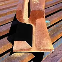
A grooved rail, groove rail, or girder rail is a special rail with a groove designed for tramway or railway track in pavement or grassed surfaces (grassed track or track in a lawn). The rail has the railhead on one side and the guard on the other. The guard provides accommodation for the flange. The guard carries no weight but may act as a checkrail.
Grooved rail was invented in 1852 by Alphonse Loubat, a French inventor who developed improvements in tram and rail equipment and helped develop tram lines in New York City and Paris. The invention of grooved rail enabled tramways to be laid without causing a nuisance to other road users, except unsuspecting cyclists, who could get their wheels caught in the groove. The grooves may become filled with gravel and dirt (particularly if infrequently used or after a period of idleness) and need clearing from time to time, this being done by a "scrubber" tram. Failure to clear the grooves can lead to a bumpy ride for the passengers, damage to either wheel or rail and possibly derailing.
Girder guard rail
The traditional form of grooved rail is the girder guard section illustrated below. This rail is a modified form of flanged rail and requires a special mounting for weight transfer and gauge stabilisation. If the weight is carried by the roadway subsurface, steel ties are needed at regular intervals to maintain the gauge. Installing these means that the whole surface needs to be excavated and reinstated.
Block rail
Block rail is a lower profile form of girder guard rail, where the web is eliminated. In profile it is more like a solid form of bridge rail with a flangeway and guard added. Simply removing the web and combining the head section directly with the foot section would result in a weak rail, so additional thickness is required in the combined section.[2]
Prefabricated grooved rail
A modern version of the grooved block rail has a lower mass and is inserted into a prefabricated spanning concrete girder such as the LR55 [3] without web but fully supported by noise reducing polyurethane grout or a girder rail such as P-CAT City Metro [4] is embedded. The prefabricated units if used with ultra light trams can be embedded into existing road base with possibly a reduced requirement for underground services diversions.
Track gauge
Electrification
Electrification needed other developments, most notably heavier rails to cope with electric tramcars weighing 12 tonnes rather than the 4 tonne horse-drawn variety; switching points, as electric trams could not be pulled onto the correct track by horses; and the need for electrical connections, to provide the return path for the electric current, which was usually supplied through an overhead wire.
Conduit and stud systems
In some cities where overhead electric cables were deemed intrusive, underground conduits with electrical conductors were used. Examples of this were New York, Washington DC, Paris, London, Brussels and Budapest. The conduit system of electrical power was very expensive to install and maintain, although Washington did not close until 1962. Attempts were made with alternative systems not needing overhead wires. There were many systems of “surface” contact, where studs were set in the road surface, and energised by a passing tram, either mechanically or magnetically, to supply power through a skate carried under the tram. Unfortunately these systems all failed due to the problem of reliability and not always turning off after the tram had passed, resulting in the occasional electrocution of horses and dogs. Since 2003, a new system of surface contact has been installed in the Bordeaux tramway by Alstom.
Cable haulage
Prior to the universal introduction of electric power, many tramways were cable hauled, with a continuous cable carried in a conduit under the road, and with a slot in the road surface through which the tram could clasp the cable for motion. This system can still be seen in San Francisco in California as well as the system of the Great Orme in Wales. These needed a rather more substantial track formation.
Gallery
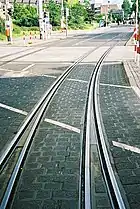
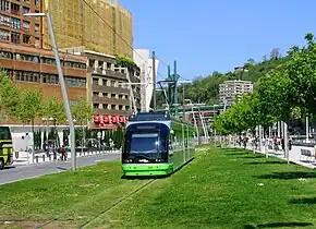 Grassed track
_light_rail_station.jpg.webp) Light rail tracks with concrete railroad ties (sleepers)
Light rail tracks with concrete railroad ties (sleepers) Joining tram tracks using an exothermic weld
 A rough exothermic weld after removal of the mould
 An intersection with the pavement removed, as workers repair the tracks for the Toronto streetcar system
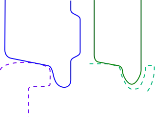 Difference in form and profile of the wheel and the rail of a train (left, blue) and a tram (right, green).
See Railway wheel flange. Temporary, or Californian, points installed on tramline 81 at junction of Avenue Louise and Rue Bailli, Brussels, on 11 July 2018
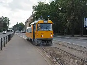
 Tram rail
See also
References
- ↑ Vandenbulcke, Grégory (July 2013). "Predicting cycling accident risk in Brussels: an innovative spatial case-control approach". Accident Analysis and Prevention. 62: 341–57. doi:10.1016/j.aap.2013.07.001. PMID 23962661. S2CID 6174483.
- ↑ Grooved or girder rail
- ↑ LR55 prefab rail
- ↑ P-CAT City Metro rail
External links
![]() Media related to Tram tracks at Wikimedia Commons
Media related to Tram tracks at Wikimedia Commons
- LR55 Track System Full details
- LR55 track suppliers and advisers
- European Girder Guard Rail Sections and Tram/Street Car Grooved BLOCK Rail without Web
- Testing Girder Rail on the MBTA.
- Wirth Girder Rail
- Grooved or girder rail
- MRT Track & Services Co., Inc / Krupp, T and girder rails, scroll down.
- Block rails
- ThyssenKrupp grooved rail
- Hilton, George W.; Due, John Fitzgerald (1 January 2000). The Electric Interurban Railways in America. Stanford University Press. ISBN 978-0-8047-4014-2. Retrieved 10 June 2014.
